

Data Transmission- Modes |Transmission Errors| Modes of Switching
MODES OF DATA TRANSMISSION
The digital messages may be sent in parallel on a number of parallel conductors or in series on a single conductor. For example, if a byte is to be sent in parallel, it would take eight wires (1 bit on one wire). In serial transmission, the same data may also be sent on a single conductor as a stream of bits. Obviously, the serial transmission is cheaper over long distances, Over very short distances, any one may be used. Inside a CPU, the circuits are designed in parallel and additional circuitry is needed to convert it into serial transmission. Over very long distances, the digital signal is converted into an analog signal, which is carried on carrier waves (by modulating the carrier wave which is also called the carrier signal) to the destination employed for modifying the carrier signal waves: performs modulation and demodulation is called modem. Any one of the following techniques may be
- Amplitude modulation
- Frequency modulation
- Phase modulation
TRANSMISSION ERRORS & THEIR CONTROL
During transmission of messages, errors may creep in because of several reasons. Several methods are used to detect the errors. A message M is sent from a source to a receiver R. If R finds that the message received is correct, it sends back an acknowledgment to S so that the source S can send the next message. However, if R finds that there is an error, it discards the message and sends a request to resend the message. The source keeps a copy of the message for this eventuality.
Methods of Checking Errors
Several methods are employed to check whether the transmission has been correct. One of the earlier methods is to check whether the number of bits sent is even or not. If the message contains an odd number of bits, the source S would add a bit to make it even. This method is not satisfactory because if two errors occur, these would make the bits even and the receiver cannot make out if an error has occurred. So along with the evenness, the total number of bits may also be tallied; in some method, the total number is processed (divide, etc.) and the source also sends the result of manipulation along with the message. At the receiving end, a similar processing is done and the result is tallied with that sent by the source. If the two tally, it is assumed that the message is received correctly.
MODES OF SWITCHING
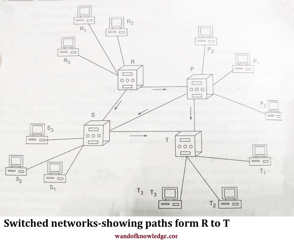
For a message to be transmitted from a source to a destination, some kind of circuit has to be established. This may be done by temporarily switching on the various switches on the way. Figure given below shows a network in which R, P, S, and T are the nodes with switches and clients connected to each are represented by subscripts, such as R1, R2, R3, and S1, S2, S3, etc. If R1 wants to connect to S2, then one circuit could be R1 → R→S→ S2. R1 is already connected to R which makes a connection with S and S makes a connection with S2. It may also take other routes as shown by arrows. According to the technology adapted, the following types of switching may be realized:
- Circuit switching
- Message switching
- Packet switching
Circuit Switching
In circuit switching, a temporary circuit path is made by switches from source to destination; then the message is passed through the circuit and the circuit is later broken down.
During the period the connection is on, no other connection can intervene. Landline telephones are the best example of this. The disadvantages of this technology are as follows:
- It takes long time to make connection.
- The time taken by the message part is the time it takes to travel down the line which is generally very small.
- The process is inefficient due to the time taken in switching the circuit.
Message Switching
In message switching, the connection is permanent, and messages are sent one after another. At th- source point, the address of destination is added to the message and is put to the network. The messag travels from one node to another till it reaches the destination. At every node, it is temporarily store and pushed on; so it is also called store and forward process. The store is required for error correction during the transmission, as described above. A disadvantage of this method is that a very large memory is required at each node.
Packet Switching
In packet switching also, the connections are permanent, but, at the source point, the message is divided into several tiny packets and information of source address, destination address, and the number of packets in the message, and the position of each packet in the array of packets is added to each packet and sent.
The different packets may travel along different paths, taking different times and may reach destination in any order. At the destination, the packets are arranged into their proper sequence and the whole message is constructed. The main advantages of this technology are the following:
- Low memory is needed at the nodes for the store-and-forward process.
- The circuit can be used more efficiently. The idle paths may be usefully employed.
- Different message packets may be intervened by message packets of other messages because now every packet has a destination address and the message it belongs to.
Important links
- Generations of Computer- First to Fifth Generation
- Central Processing Unit | Parts of CPU
- Operating Systems- Windows | UNIX | Linux |Function of an OS
Disclaimer: wandofknowledge.com is created only for the purpose of education and knowledge. For any queries, disclaimer is requested to kindly contact us. We assure you we will do our best. We do not support piracy. If in any way it violates the law or there is any problem, please mail us on wandofknowledge539@gmail.com